


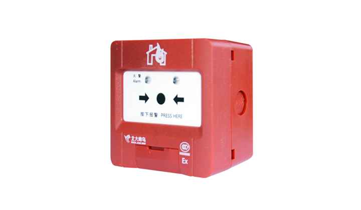


JBE-2120
Applied to EN standard, connect to the loop, monitoring the fire protection equipment. When the dry contact of the module is closed, fire alarm or supervision signal is sent to the control panel


| Category | EN 54-18 input module |
| Working voltage | DC 16-30 V (JBE protocol pulse amplitude) |
| Connection | 2-wire JBE communication bus, no polarity |
| Wiring | Twisted pair, max. wire section 2.5 mm2 |
| Quiescent current | ≤0.25mA @24V |
| Activation current | ≤1mA @24V |
| EOL resistor | 10 kΩ |
| Working temperature | 0 to +40℃ |
| Storage temperature | -20 to +50℃ |
| Environment Humidity | ≤ 95% RH (no condensation nor icing) |
| Addressing method | Soft addressing with tool JBE-AT1, non-volatile |
| Address range | 1-200 |
| LED Indications | Standby:"Input" LED flashes when polled Constant on when active Fault:"Input" is off. Activation:"Input" is constantly on. |
| Dimensions | 85 mm ×85 mm x41 mm |
| Weight | 0.1 kg (including base) |
| IP rating | IP40 |
| Standards | En 54-18:2005+AC:2007 |
| Declaration of Perf. | DoP-0370-CPR-3805-1 |

| Terminals | Connection |
| 4&5 | Signal loop L1, L2 (no polarity) |
| 9&10 | Connect equipment in the field: AS+, AS-. Install the 10 kΩ resistor (provided with the unit) at the furthest end of the cable, in parallel to the NO switch in the field equipment that is monitored. |